m|ars
Airflow resistance measurement system
The measurement of airflow resistance with m|ars enables convenient determination of the airflow resistance in quasi-static airflow. The airflow resistance in quasi-static airflow describes the behavior of the specimen at very low air velocities, as typically occur with sound waves.
Typical applications of airflow resistance measurements:
- product development of sound absorbers:
By means of the airflow resistance the suitability of materials such as fabrics, fibers and foams for sound absorption can be estimated and acoustically optimized. - quality assurance in the production of sound absorbers:
The airflow resistance is a quickly measurable variable, that reacts sensitively to acoustically relevant product fluctuations. - determination of characteristics for numerical simulations:
Almost all numerical models of porous absorbers include the airflow resistance as an essential input parameter.
m|ars uses the quasi-static airflow method described in the ISO 9053-1:2018 standard to measure the airflow resistance. A constant volume flow is passed through the sample. At the same time, the increase of pressure in front of the sample referred to the atmospheric pressure behind the sample is measured. The ratio of pressure difference and flow velocity results in the airflow resistance, which is independent of the flow velocity for most porous materials. According to ISO 9053, the airflow resistance divided by the sample surface is called specific airflow resistance. The specific airflow resistance extrapolated or interpolated to a flow velocity of 0.5 mm/s is given as a single number. This flow velocity corresponds to the sound velocity of a plane sound wave at a sound pressure level of approx. 80 dB.
Different specimen holders can be mounted on the pressure cylinder for the examination of different specimens: Thin specimens such as fabrics or felts are clamped onto a circular flange, while thick, flexible specimens can be pressed to a specified thickness using a special cylindrical specimen holder. A set of cylindrical specimen holders of different lengths makes installation and sealing of specimens of different thicknesses easier.
Technical data
- volume flow adjustable between 0.1 lN/min and 6 lN/min
- differential pressure measurable between 0.02 Pa and 10 Pa
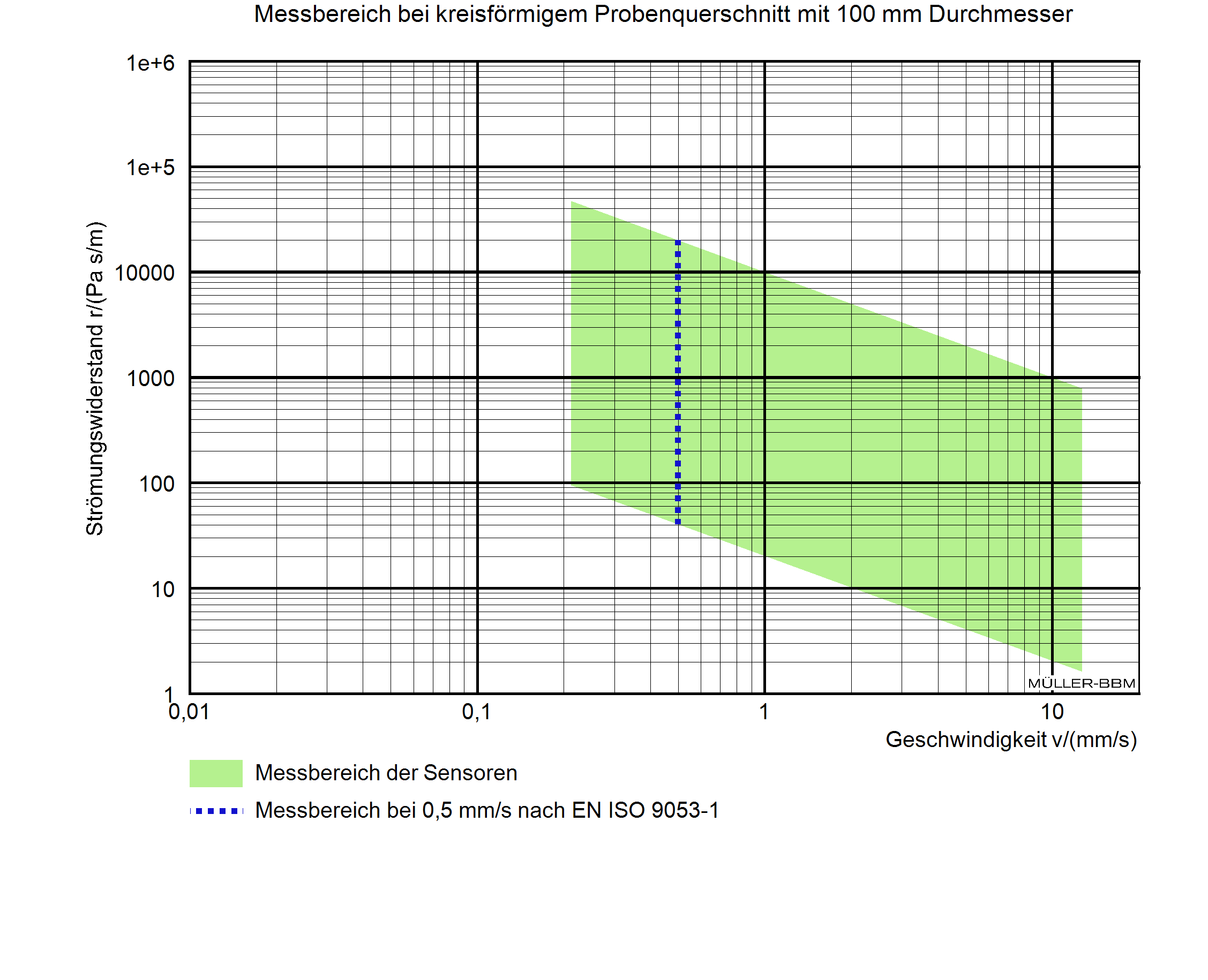
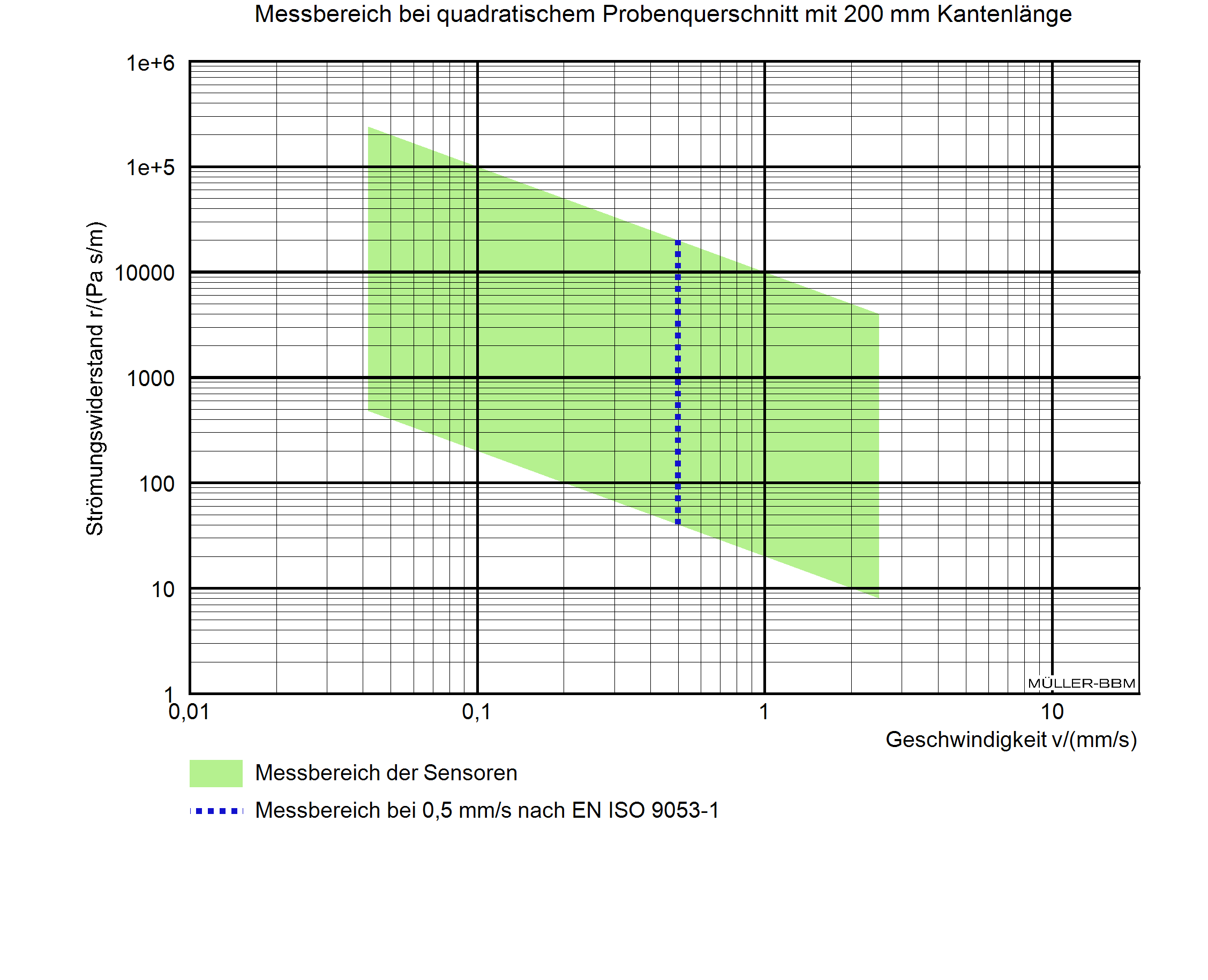
- measurable specific airflow resistance between 40 Pa s/m and 20,000 Pa s/m at a flow velocity of 0.5 mm/s
The measuring range for the specific airflow resistance results from the measuring ranges of the differential pressure sensor (0.02 Pa … 10 Pa) and the volume flow controller (0.1 lN/min … 6 lN/min), as well as the normative recommendation to measure down to a flow velocity of 0.5 mm/s. For the specific airflow resistance, this results in a lower limit of approx. 40 Pa s/m and an upper limit of approx. 20,000 Pa s/m. If lower or higher flow velocities than 0.5 mm/s are permitted, the available measuring range depends on the cross-sectional area of the specimen through which the flow passes. The measuring ranges are shown in the figures as examples for a circular and square specimen cross-section. In practice, specific airflow resistances from approx. 10 Pa s/m can be determined.
Scope of delivery
- pressure cylinder for mounting various specimen holders
- specimen holders for the measurement of thin, pressed or thick samples with an inner diameter of 100 mm
- optional: additional specimen holder with square cross-section according to customer requirements
(e. g. 150 mm x 150 mm or 200 mm x 200 mm) - measuring unit with integrated pressure reducer, volume flow controller, differential pressure gauge, air pressure sensor, as well as sensor for measuring temperature and humidity in the pressure cylinder; all components with factory calibration on traceable DKD or equivalently calibrated reference measuring devices
- hole template for preparation of flat specimens
- 2 reference airflow resistances
Conditions for operating the measuring device
- dry and oil-free compressed air supply with an overpressure of at least 1 bar and a maximum of 15 bar, connection with quick coupling NW 7.2
- installation site with air pressure fluctuations that are significantly lower than the minimum differential pressure occurring during the measurement
The included software m|ars is convenient and easy to use and is characterized by the following features:
- intuitive operation of the user interface, adapted to the measurement process
- individual configuration and central storage of preferences for fast and automated execution of measurements incl. automatic measuring range determination
- release of an individual test report with tabular and graphical representation of the measurement data and results for different languages
- program interface in English or German
- software license for an unlimited number of workstation computers
In order to use the software, a personal computer running Windows version 10 operating system with a free USB port (version 2.0 or above) is required.


