m|abstube
Impedance tubes according to ISO 10534
In the impedance tube, the surface impedance of an installed specimen is determined at perpendicular sound incidence. The sound absorption coefficient and the reflection factor can be calculated from the surface impedance.
With an extension of the impedance tube, the transmission or the sound reduction index of the specimen can also be determined.
Typical applications of impedance tubes:
- product development of sound absorbers
- quality assurance in the production of sound absorbers
- determination of characteristics for numerical simulations
- determination of the sound reduction index (special application)
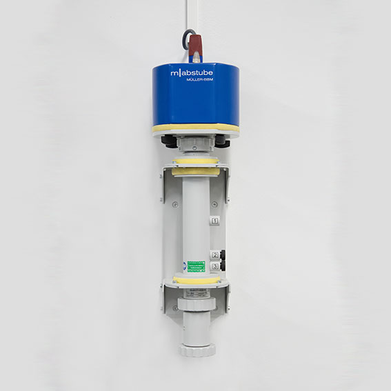
Impedance tubes consist of tubes with a round or square cross-section and are terminated on one side with a loudspeaker and on the other side with the test object and a reflective tube termination. The loudspeaker is used to excite plane sound waves in the impedance tube, of which the sound pressure is recorded by microphones located between the loudspeaker and the test object. The surface impedance can be calculated from the determined sound pressures and the geometric distances between the microphone positions and the test object. The sound absorption coefficient and the reflection factor are calculated from the surface impedance.
As a special application, the sound transmission, i. e. the sound insulation, can be determined by means of an extension tube. The extension tube is connected to the main tube instead of the reflecting tube termination, contains as many microphone positions as the main tube and terminates with an anechoic swamp. The anechoic termination is realized by a wedge absorber placed in the extension tube. For the determination of the sound transmission, the sound pressures at the microphone positions in the main tube and in the extension tube are determined.
The use of an impedance tube to determine sound insulation can be useful for test objects whose vibration behavior is representative for the intended application despite the small sample dimensions. This includes many porous absorbers such as fabrics, foams and fibroid materials, but also sealing profiles.
Our impedance tubes at a glance
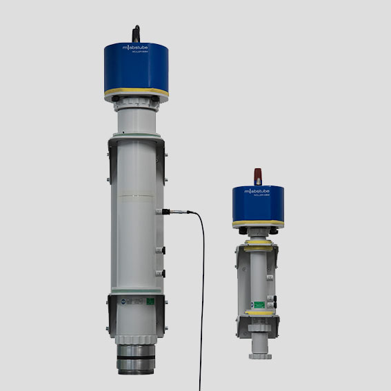
| m|abstube D30AL | m|abstube D100AL | |
|---|---|---|
| Inner diameterD | 30 mm | 100 mm |
| Lower operating frequency flow 1 | 200 Hz | 90 Hz |
| Upper operating frequency fhigh 2 | 6500 Hz | 1950 Hz |
| Number of microphone positions | 3 | 3 |
| Maximum distance of the microphones dmax | 83 mm | 190 mm |
| Minimum distance of the microphones dmin | 20 mm | 71 mm |
1 determined by the maximum distance of the microphones dmax and the measurement uncertainty of the phase: e: flow = 0,05 * c / dmax
2 determined by the inner diameter D and the acoustic velocity c: fhigh = 0,58 c / D
Scope of delivery
- impedance tube with three microphone holders for 1/4“ microphones and loudspeakers
- wall bracket for vertical mounting on a wall
- extension to determine the transmission coefficient: impedance tube with another three microphone holders on the receiving side and anechoic termination (for D100AL only)
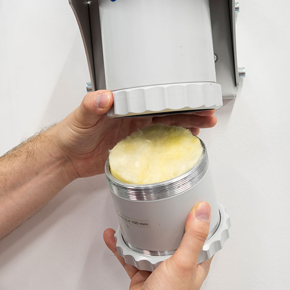
- various tubes for screwing onto the impedance tube as specimen holder
Measurement system
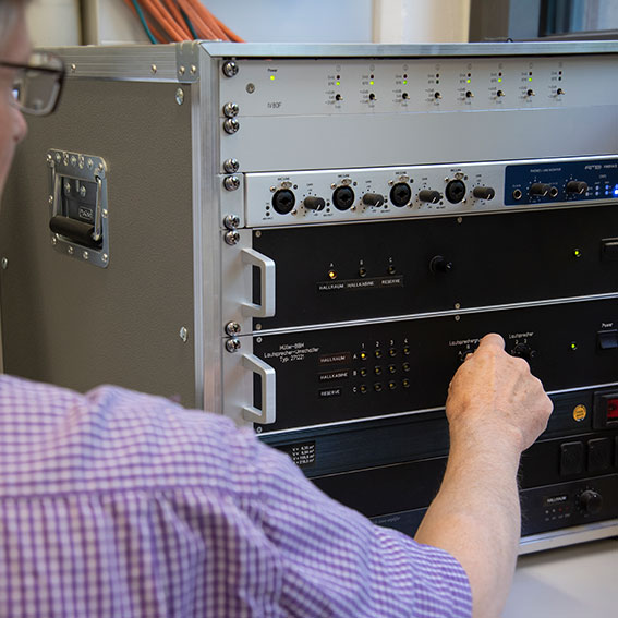
- 1/4“ microphone and signal conditioning
- audio interface (audio sound card with at least two input channels and one output channel, depending on the application)
- power amplifier
The software m|abstube is universally suitable for all impedance tubes. The individual geometries of the impedance tubes can be stored by the user in the options of the software.
- control of an audio interface for measuring the sound pressure signals
- free selection of loudspeaker and microphone channels of the audio interface
- generation of any swept sine signal for measuring the impulse responses
- display of the measurement result directly after the measurement
- analysis tools for graphical display of measured raw time data and impulse responses in the time and frequency range
- evaluation in 1/3, 1/12 and 1/24 octave bands and FFT resolution
- freely selectable averaging of measurement results over different samples, also from measurements in different impedance tubes to extend the frequency range
- comparison of the results of several samples in one diagram
- automatic creation of freely configurable result sheets with tabular and graphical display of the measurement results in German, English, Italian or French
- program interface in English
In order to use the software, a personal computer running Windows version 10 operating system with a free USB port (version 2.0 or above) is required.


